C 819 Magnetspule (Solenoid) Problem

  • Hello Dual Fans!


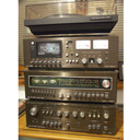
    I'm not sure if English is allowed here, but let's give it a try as "Made In Germany" stays on front of Dual amplifiers, tuners and decks. I have a pleasure to own a beautiful C819 deck wich seems to have some logic/solenoid problem. The solenoid, which normally acts as auto-stop actuator, should turn off after each activation in miliseconds. In my C819 it needs about 15 second to switch off. The effect: if I press play/fast forward/fast backward key the deck works normally. But give it any occasion to activate the solenoid (e.g. end of cassette or manually stop the right spindle when no cassette in) and the next time I try to press play/ff/bw - in a moment that motor starts - a solenoid turns on and stays on for about 10-15 seconds.


    I discovered that solenoid voltage stays high for a moment and then is gradually lowering (almost linear) till the electromagnetic field is too week to cancel play/ff/bw keys. The signal from phototransistor seems to be OK (0,6 V or 11 V measured at B10 or R4201 when right spindle stationary depending on a precise spindle positioning). The transistors T4200/4201 work properly, with T4201 trigerring the solenoid when a base voltage reaches 0,6 V.


    What's interesting is that after triggering the solenoid both transistors stay open and the base voltage decreases very slowly, like there was some capacitance in the circuit that needs to be discharged. Moreover, when I turn the deck on after long period of time and press play/ff/bw, the solenoid turns on for some 10-15 seconds (I need to keep the play/ff key pressed manually to observe that and measure solenoid voltage).


    So it seems that my C819 starts with its solenoid "ready to go" be default :) Any help appreciated - maybe it's a common issue with this model and you know how to fix it. I can understand German with no problem, only my writing turned into forgotten skill. I would be more than happy to know, how the logic circuitry should work and what is the principal of the automation provided by TIL 621, IC 4201 and all the gates.


    As far as I know, the signal from phototransistor is being filtered by capacitors, and this way the triggering signal for solenoid is led further only when it's not steady, preventing T4200/4201 from opening. When the right cassette spindle stopps, TIL 621 provides a minimum or maximum steady voltage and this triggers the solenoid. Another interesting thing: the voltage before/after the D4208 diode is 0,8 and 11 V. Overall I can measure some voltages at least twice too high for a logic gates - I expected some 5V there - but I assume this is not a typical AND gate appliance.


    Another observation: with no cassette inside, I press FF, keep the right spindle with fingers (so that it doesn't rotate) and observe sonenoid voltage. It stays high and constans. But when I release fingers from the spindle and the phototransistor starts to register alternating light/no light states, the solenoid voltage begins to lower gradually till the solenoid turns off.


    My C819 needs your help to get fit.


    All the best,

    Mike

    Dual CV1400 + CT1440 + C819 + CS704 + Revox BX 230

    Dual CV20 + CT15 + CS20 + Blaupunkt Lab 208

  • Hi Mike,


    interesting problem.... your understanding of the basic function of the circuit is correct.

    From my point of view the most suspect behavior is the slowly decreasing base voltage at the transistors after the solinoid activation. You´re right - there must be a power supply where it shouldn´t be 8-)

    Please check S17 (I assume, you have the schematic avilable) - if in the STOP-position the contact to ground is not proper, then the remaining turning of the flywheel / motor (now serving as generator) provides still power to the transistors driver circuit - thus the transitors remain opened for a while, although they shouldn´t..


    Have a try and let us please know the outcome.


    Best regards,


    Armin

  • Please check S17 (I assume, you have the schematic avilable) - if in the STOP-position the contact to ground is not proper, then the remaining turning of the flywheel / motor (now serving as generator) provides still power to the transistors driver circuit - thus the transitors remain opened for a while, although they shouldn´t..

    Hi Armin,


    S17 has a proper grounding in idle position and solenoid turns off immediately when the motor stopps (releasing the play/ff key). So the energy source that keeps discharging when solenioid remains active for several seconds must be somewhere else. Two by-the-way clues:


    1) There is a D4208 diode that brings suspicious readings on the multimeter (the diod remains on board as there is no comfortable reach for unsoldering it before measuring) - a voltage drop is 0,6-0,7 V in one way and some 2,5 V with switched polarity but that might be the case of other components overtaking the current flow (measured wnen the deck is off),


    2) The scheme shows IC4201 as MC14011B but... Such IC has NAND gates, and Dual service scheme contains four AND gates. To achieve this, the IC should be BC14081B - so which statement is truth:


    a) the gates in the service manual are AND type but Dual has mistaken an IC type,

    b) the IC type in service manual is correct, but the gates should be NAND type on the schematic,


    ...the answer is b) because what's in my C819 on logic/power supply board is actually IM14011B with no doubt :) That makes sense because there would be no point in shorting two inputs of AND type gate together, where such shorting in case of NAND gate brings NOT gate on board. Moreover, as two AND gates with shorted inputs in series make no sense, two NOT gates can potentially fix issues with switching glitches and signal power and timing.


    That assumption stopped me from analyzing the deck based on service manual for a moment, maybe together or with help from others we will be able to say what type of gates should be on service scheme. I obtained one form radiomuseum.org:


    https://www.radiomuseum.org/r/dual_c819c_81.html


    So the solution remains open, and my C819 is still waiting for opening it's auto stop solenoid.


    Thank you for your engagement with all my heart as it may start the Dual's heart beating again :)


    All the best,

    Mile

    Dual CV1400 + CT1440 + C819 + CS704 + Revox BX 230

    Dual CV20 + CT15 + CS20 + Blaupunkt Lab 208

  • Hi Mike,


    this is all weird somehow...8-)


    Concerning the diode: I guess when the "deck is off" it is powered, but in Stop condition - the voltage you can measure between the diode pins should have value of some mV, + at the cathode. If the motor is runing, this voltage changes between two values: fixed ~0,6V and some (m)V, depending from the rotating speed. This change is always accompanied by a polarity change!

    Has your multimeter a function selection position marked with a diode symbol? This stands for diode check, heyhey 8-) If yes, then you can test the diode while the 819 is switched off (unpowered!) w/o desoldering it to get clearness about the diode´s condition; if the red +wire is connected with the cathode (marked with a ring on its housing) and the black one (COM) with the other pin, the meter should show an overload "OL" or something equivalent. With exchanged connections you should see a value below 700. Otherwise the diode is defect.


    The gates are in fact NANDs (MC14011) - otherwise the logic wouldn´t work. My service manual (an original paper version) shows the same circuit with NANDs like that one stored here under "(ext.) Anleitungen" ***Click*** "Dual-Logo" Click *** "C 819 Service" (see above). The MC14xxx logic family operates with supply voltages up to 15V - here with 13V, thus voltages >5V you measured are OK.


    Now back to the "Ghost power supply":

    My first (mis?!)understanding of your descritption was, that when a stop operation occures (cassette end reached or manually), the solenoid switches off the motor (and the mechanism), but T4200 still receives afterwards a decreasing base current/voltage for some seconds and that keeps the solenoid active over this time. That´s not the case, isnt it? The solenoid is immediately switched off after it has deactivated the motor / mechanism and the voltage at pin 14 of the MC14011 decreases quickly to ~0V, when the stop operation is initiated manually or by the cassette end - that fits to my understandig when S17 operates properly 8-)


    BUT: If you press Start and the machine runs up, the solenoid becomes active immediately and remains active with decreasing base voltage at T4200 for several seconds - to supress the Stop operation you have to keep the Start button pressed for that time and afterwards the machine runs as it should. Is this correct?


    Best regards,


    Armin

  • Hi Armin!

    To this time I have made so many measurements in almost all the points of the circuit (gates, switches, transistors etc.) that I need to get some traction before showing what I found - otherwise I would have to spam with a hundred of multimeter readings. But - to the point:

    Has your multimeter a function selection position marked with a diode symbol? This stands for diode check, heyhey 8-) If yes, then you can test the diode while the 819 is switched off (unpowered!) w/o desoldering it to get clearness about the diode´s condition; if the red +wire is connected with the cathode (marked with a ring on its housing) and the black one (COM) with the other pin, the meter should show an overload "OL" or something equivalent. With exchanged connections you should see a value below 700. Otherwise the diode is defect.

    Yes, I used multimeter's diode testing mode and the readings I mentioned were measured with the diode on board, deck in STOP position and unplugged from 230 V. The voltage drop one way was about 0,6 V and the other way about 2,5 V. So it seems that the diode is out of order or that is a metter of other components on the board. Moreover, today I discovered that C4209 has zero capacitance but connecting similar capacitor in parallel does not chang the solenoid behaviour. Second topic you mentioned:


    "BUT: If you press Start and the machine runs up, the solenoid becomes active immediately and remains active with decreasing base voltage at T4200 for several seconds - to supress the Stop operation you have to keep the Start button pressed for that time and afterwards the machine runs as it should. Is this correct?"


    - yes that's exactly the case. So I've spent the day examining two topics:


    1) In other decks that I know when you press the fast rewind key without cassette and keep it depressed with a force of your finger, an auto-stop solenoid doesn't just simpli turn on - it rather acts with impulse every say half a second. In my C819 it just turns on and stays on all the time I keep the fast rewind (right spindle stationary) key. So I started to look for a point in the solenoid's activating circuitry where such umpulses occur when keeping fast rewind pressed without cassette. I started form T4201 backwards and I found out that:


    - on a base of T4201 there are minor 10 mV fluctuations on a steady 600 mW with a period of about one second,

    - on an emiter of T4200 there are 2 V fluctuations, lowering a steady 8 V to 6 V with the same period as above,

    - on both sides of C4211 (pins 9 and 11 of NAND gates) there are similar impulses observed, up to 10 V in peaks (but this time it was measured with digital auto multimeter which shows strange values due to its higher impedance),

    - on both sides of C4210 there are also impulses, from 0 V to 2 V peaks on NAND pin 10 and from 2 V to 4 V on NAND pin 12, measured with analog multimeter,

    - on 8th pin of NAND there is a steady 3V with no impulses.


    Bingo - the problem starts from this point all the way to T4201. From my modest and for sure incomplete point of view, the solenoid should be driven by these impulses and switch off between them, which does not happen. This is a topic for further examining as I believe that the circuitry from D4208 to T4200 should be responsible for triggering solenoid with impulses not a steady voltage. Now the second:


    2) This time I also started from T4201 backwards and was looking for a point on the triggering signal where there's no "memory" or "RC" effect, in other words the voltage drops immediateli after activating auto stop. On almost every point of the circuitry from T4201 to NAND gate pins 9, 10, 11, 12, 13 and their surrounding elements, after activating auto stop something happens to the voltage (once the voltage becames lower, in other points higher) and then it needs several seconds for the signal to come back to the "normal" value when the solenoid is off. The testing was done without cassette and Fast Forward key presset with a force even when solenoid turned on. The first point in the circuitry, looking from T4201 backwards, where the signal noticed a peak when the right spindle stopped (with a finger) and then immediately reached the normal value, is the NAND gate pin number 8. When fast forwarding, there is near zero volts there, but when the right spindle stopped (with a finger again) the voltage increases and at about 3 V DC the solenoid turns on. When I let the right spindle running again when still pressing Fast Forward key the voltage immediately reaches normal near-to-zero volts again. So at this point the problem starts on the triggering signal's flow.


    The next thing I will do is to find out where do the steady high voltages come from in D4208-T4200 (base) part of the circuitry. And where is the misterious "capacity" that "loads" when a solenoid is activated and then "discharges" for 15 seconds, keeping T4200 and T4201 open. Another question mark is the use of both analog and digital multimeters. They sometimes show very different values. The digital one is a UNI-T junk but I hope that a model UT139S should at least show anything reasonable even if it is not a Fluke. But there were some points with I think abnormal values measured with both analog and digital multimeters: when force pressing the Fast Rewind key without cassette I measured some 9 V DC on a T4200 base. This is not a TTL value I expected - where did such a voltage come from as this is a NAND gate output :)


    I also observed that when solenoid is active the +G voltage drops by 0,9 V. Multimeter connected to +G shows +14,4 V with the deck off, 13,1 V with the motor running and... 12,2 V when the solenoid is active. But the solenoid is driven by +A 24V which remains steady as this power supply is a stabilised one. How come? Is it possible that even when the 24V remain the same when the solenoid turns on the current becames higher and that alters the magnetic fields of the trafo and theroetically independent +G drops by 9V? Or maybe something on the board is draining the current form +G? I will acomplish the same measurements with solenoid unplugged and see what happens.


    That's only a modest part of investigation :)


    But as we solve the problem maybe sometime somebody will profit from the research done.


    Oh, didn't mentioned that there is no C4200 on board but there is a burned R4216 so maybe a peak in voltage when C4200 had a shorting did some harm to the logic circuitry.


    No surrender :)


    Regards,

    Mike

    Dual CV1400 + CT1440 + C819 + CS704 + Revox BX 230

    Dual CV20 + CT15 + CS20 + Blaupunkt Lab 208

  • Hi Mike,


    OK, let´s see, what we have:

    during power up the circuit might produce a short activation pulse, but this will not last long enough to activate the solenoid - a properly working MC14011 gate as wired as it is here would not allow a decreasing or increasing output voltage (push-pull driver!) over several seconds.The involved capacitators are too small to create "side effects" and it´s unlikely that one of them is somehow defect, because they are not electrolythic ones. With one exception: C4208 - theoretically this one might be shortened internally (often observed damage), but then the soleonid could never be activated. The observed slow voltage decrease might be possible, when the low side FET of a gate is no longer able to provide a sufficiant current to ground... this can also be caused by a "cold solder" at pin 7 or 11 of the MC14011.


    Concerning the voltage shifts: the 24V +A voltage is stabilized by IC4200, thus the different electric load currents at the transformer do not cause here a change as long as the input voltage at IC4200 doesn´t drop below ~26,5V - the other effects you descibed are OK, but when did you see a drop on +G by 9V (lamp gets dark?)???


    To be honest: I can not follow all the descriptions of the measurements you made, so let me propose following proceeding:

    - please re-sold all solder points of the parts of the solenoid driver circuit.


    - please check also if the switches S18, S19 and S20 work properly.


    If the re-soldering doesn´t fix the problem, then

    - pease measure in unpowered state the resiance of R4202 to R4208; the measured values might stabilize over some time after the cables are attached, caused by one or another capacitor. Repeat these measurements also with exchanged cables. Please note the measured values and the corresponding polarity of the measurement cables (+ red / + black), referenced to pins of other components connected to them.


    - For asurement: please measure the resistance of the capacitor C4208 with the red + cable attached to its + pin - here you should measure after some time a stable value NOT lower than several 10th kOhms!


    In fact, from my point of view the MC14011 is the most suspicious candidate 8-)


    Best regards,


    Armin

  • Hi Armin,


    my mistake with a +G voltage drop - it should be 0,9 V instead of 9 V. The good news is that I was able to simulate the circuit online during one of the "sleepless nights with Dual" and here you can find the effect: https://tinyurl.com/ydr6nvfy After fine tuning the parameters of several elements the circuit works as it should and I was also able to simulate its abnormal behaviour that I know from my C819 by virtually disconnecting the 0,33 uF C4209 in online circuit simulator. So maybe it's a matter of this capacitor even if it sounds lika a minor possibility.


    For me - "Dual home technician" as a hobby :) - learning how the solenoid's circuitry works is a fantastic journey through the magic of digital-analog electronics. I signed for several courses on electronics design and bought some measurement equipment just to keep my Dual audio components fully functional and technically healthy. And without a simulation (from the link) I would hardly be able to imagine what's actually happening in the Dual's solenoid driver, ecpecially interesting is C4207 acting as a voltage doubler when the spindle is running and a combination od D4208 and C4209 blocking the "high" signal from the second NOT gate. I'm an amateur and all the states that occur in the analog-digital circuitry just wake up my passion to old good electronics design, where you can measure almost every voltage you want - on the contrary to a modern audio equipment with a lot of IC's.


    Another interesting thing: a datasheet of MC14011B says that it can handle high power supply voltage but the signals on the gates should be between 0 and 5V. In the C819 the gates handle some 18 V on the input (driven by C4207) and otput even 12 V. I know that some CMOS IC's have V(high) and V(low) levels not fixed but based on a certain percentages of a supply voltage but I thaught that MC14011 was not one of them - it seems I was wrong. Finally, I ordered MC14011B, 1N4148 D4208 and 330nF C4209 (a rare silver capacitor) and will give it a try. Although I'm not a fan o "let's replace some elements and see if the problem is fixed" method, at this stage of analysis there are not many remaining options.


    I will also check everything you mentioned and maybe use oscilloscope to further examine the signals surrounding the MC14011B. Important question or rather a modest request: could you please guide me how to get the whole power supply/erase signal generator/MC14011B board out of it's metal housing? It sits in a U-shaped piece of metal so tight that the only thing that comes to my head is to use force to unbend the U-shaped housing and let the PCB free. I know there is a small metal blocker I need to handle with pliers but this does not free the PCB for service access.


    Your knowledge and willingness to help are impressive and I really appreciate that.


    Regards,

    Mike

    Dual CV1400 + CT1440 + C819 + CS704 + Revox BX 230

    Dual CV20 + CT15 + CS20 + Blaupunkt Lab 208

  • Hi Mike,


    nice idea to simulate the circuit! But I still do not see the reason for that slowly decreasing output of the gate driving T4200... never mind, your strategy is OK.


    The CMOS logic chips are working with logic voltage levels corresponding to the supply voltage; at 5V supply, a HIGH input level is represented by a voltage > 3,5V, at 15V supply by a voltage >11V. Please have again a look into the data sheet. Outputs provide similar voltages when they are "push-pull" types (the MC14011B has this type), in case of open drain/collector outputs the max. allowed load is defined as max. allowed current. 18V input voltages might scratch the upper allowed value...


    Concerning the disassembly - unfortunaely my 819 is actually more than 400km away from my home, so I can not have a look inside. And the original service manual is the lousiest (but complete) one I have - neither a population plan of the PCB nor a picture of the housing parts arrangement are included!

    I guess you must remove the rear plastic cover and eventually the right side board first and then an access/disassembly might be possible... but don´t apply high forces - keep in mind that with high likeliness the machine was mounted by tender women 8-)


    Good luck!


    Best regards,


    Armin

  • Hi Armin,


    finally I managed to connect the oscilloscope to several points of the C819 solenoid triggering circuit. So I have results from measurements with an analog multimeter (low readings), digital multimeter (higher readings) and chinese tablet-oscilloscope machine :) that's so good that it reads some low voltage signals as zero. Having known that I decided to trust the oscilloscope - and all the signals started to look better. The signal from the second NAND gate driving T4200 on the oscilloscope was not slowly decreasing any more - a beautiful square triggering signal was always followed by a sudden decrease in voltage, let's call it "chinese zero". But analog multimeter was still showing this "chinese zero" as some 500-600 mV at the T4200's base.


    So after oscilloscope measurements done I decided to un-sold T4200 and give it a check as it kept open at suspicious low base voltage level. Parameters outside the PCB were all OK but I replaced this transistor anyway to give it a chance. With no effect. The C4205 was also un-solded and checked because it was bringing strange readings on a multimeter when onboard - some 30-40 mF instead of 1 mF but finally this capacitor passed the test for capacity, voltage leak and inner resistance. The same situation with C4209 - no capacity onboard, perfect parameters outside the PCB.


    Chasing the last criminal on the board left the one and only NAND gate directly connected to the T4200 base as final suspect. It just seemed not to be able to keep the "0" voltage low enough for the transistor to close and deactivate the solenoid. After about one hour of fighting with desoldering tape, spring-loaded vacuum and no special equipment for chip desoldering I was able to take the MC14011B out and replace it with new one from Motorola. The problem has been immediately solved - auto stop now works perfectly under any circumstances - so I added new "Knallfrosch" capacitor and replaced its burned resistor, fine tuned counter memory contacts, closed the bonnet of the deck.


    I was more than pleased for the moment - finally my C819 was ready to be put on the top of CV1400 and CT1440, when staying under CS704. But it was just too good to be true. According to the Murphy's rules, another issue appeared. :) And now I have a problem to describe the issue precisely in English as I can not find the exact Englich counterpart for the word I could use - the best I found is "self-exciting" which may be technically absurd but let's give it a try. Here is what happens.


    The deck plays, records, and does every little thing the way it should. But once I press the Record key (alone), wait several seconds, and then press Play (with or without cassette) the VU meters go to the max and a low frequency tone comes from the speakers. When the cassette is in, the hum comes to the speakers in paralell with the cassette being played. The tone decreases in volume when pressing the Fe button and wakes up again when releasing Fe. When the deck "self-excites" and VU's go to the max with this subwoofer-like tone, you can do anything you want with any keys on the front of the deck and the hum remains active, sometimes being supressed with Fe key, sometimes the Fe button does not alter anything. You can even switch the power off and press play again - the hum is there.


    But wait a minute or two and the deck comes back to the full functionality. No hum. And now the interesting thing, that seems familiar.


    When the deck is on idle and I press Record button on alone, wait about ten seconds, press Stop and then Play with no cassette inside, the right VU meter moves a bit and returns to zero after a second. The longer the Record button is pressed before Play, the higher the kick that right VU meter gets. At about 15 seconds it's clear that ther must be some capacitance, as the VU hum leves starts from higher readings and decreases slowly, like when discharging some capacitor. Wait 20 seconds with Record button pressed on alone (motor not running, no record signal on VU) and then Play and the full power hum self-excitation shows on the VU meters - both to the max. If that happens, as I mentioned earlier, there's nothing you can do but wait for the the hum to turn off by itself.


    I disconnected the deck from amplifier - nothing changed. I'm afraid of doing more testing with amplifier to protect it's fragile op-amps on the inputs. And even though it may look trivial, it took me some time to discover a way to wake up the self-excited hum again. Maybe someone will enjoy our discussion - the more brains, the more solutions, as in the neural networks :) These long, long posts are on purpose - maybe someone will find the described symptoms familiar and show the path to resurrection of my C819. But even if not - I still enjoy fixing this deck as it's a hobby, not a job.


    PS. You were right about the MC14011B - but knowing the de-soldering challenge I tried to avoid touching this little boy at any cost.


    Hereby I declare to keep fighting for bringing this beautiful Dual deck back to life.


    No surrender :)


    Regards,


    Mike

    Dual CV1400 + CT1440 + C819 + CS704 + Revox BX 230

    Dual CV20 + CT15 + CS20 + Blaupunkt Lab 208

  • Hello Mike,


    first congratulations for repairing the solenoid driver!

    And your new problem I also know - as I remember, the long shift switches that are responsible for the Play-Record mode change and are operated by the Record-button, must be cleaned. But you shouldn´t use WD40 or similiar products for that - their residues might damage the parts after some time. I made good experiences with Tuner 600 spray from Kontakt Chemie. CaiLube MCL is also mentioned in some forums, but I didn´t use this until now. Perhaps somebody else here as better ideas...

    In general the cleaning of all switches and plugs is somehow mandatory 8-) Often even multipe activation-dectivation cycles may help enough; the mechnical friction wipes away oxide and dirt.


    Best regards,


    Armin

  • Hello Armin,


    I will clean the S1 and S2 with a special cleaner intended for contacts and potentiometers, securing the PCB with some paper (in order not to spray the elctronics). The best solution would be a disassembly of these switches but I am not sure such demontage would be possible. So I will spray the isostats as they are on PCB. With the help from Google I also tried to move this long isostat back and forth with a record button and it looks like the buzzing is off. It is not a typical 50 Hz or 100 Hz hum from a network/power supply/grounding issues, it's like a highly randomized sine wave from a generator. For now I would like to understend my C819's schematics as a whole. I can locate the main blocks of the decks, but still being unable to draw a precise path of signal from head to line out. Seems that I need to acquire more and more technical knowledge on electronics to fully understand the function of every element in the C819. Of course it does not mean that I will be automatically able to fix my deck's problems but at least my fixing activity will turn into concious investigation.


    I think that would be reasonable to make it possible on dual-board de to run profiles of Dual audio items, I mean specific devices (not models as a whole) on facebook style manner and keep them up to date with all the issues and fixings, like in the diary. That would be a story of Duals with particular serial numbers. Such a diary would be fun and very useful at once. Anyway I could run such a profile on Facebook but that's not as intimate place for Dual lovers as here. Just an off-topiic thought. But maybe the threads dedicated to a certain model would be a better soluttion. And they may even exist without me knowing that. :)


    I will report all the updates,


    Mike

    Dual CV1400 + CT1440 + C819 + CS704 + Revox BX 230

    Dual CV20 + CT15 + CS20 + Blaupunkt Lab 208

  • Hello Armin, update here :)


    after cleaning the bar record switch (S1, S2) the deck is finally fully functional. But that's not bread and butter job as neither S1 nor S2 provide access to the contacts from the upper side of their metal housings. Both a long metal record lever (300) and the copper coupling between switches (364, 365) must be removed before cleaning. Then the spray must be applied from the front and back of S1 and S2 - a small mirror can be used to discover that only from that direction the contacts of S1 and S2 are accessible and visible. So I bent the cleaning spray's tiny plastic tube by 90 degrees and applied some cleaning fluid carefully. In order not to "clean" other components on the board, paper can be used to protect the surroundings on both sides, fornt and back of the record bar switch S1/S2. After that - the C819 got the second life again.


    For further investigation: when I press Pause and then Play, an unpleasant gearwheel noise occurs. That is because when Pause is pressed with the deck on idle, a metal lever nr 204 bites the fragile and thin gearwheel nr 227 so strong, that after pressing Play the 227 gearwheel cannot move towards the front of the deck far enough to let the 227 and 217 gears engage. The 217 slips on 227 making the noise and destroying both gearwheels. Is it a common issue/design error of C819? And shouldn't a 204 metal lever have some kind of a rubber protection to protect the 227 cogwheel? Both the tiny and delicate 227 gear and the 204 metal lever biting into thin plastic cogwheel don't appear as a durable solution but the user manual says to "press the Pause, Record and Play keys in that order" so it should work. The force with which the 227 wheel is pressed by the 204 lever when angaging Pause button at deck's idle is so high that the 227 cannot move to angage with 217. It seems impossible - the 227's position after pressing Pause is spring-loaded and if the spring were stronger, it would brake the 227 wheel or let the metal 204 lever destroy the cogwheel. Maybe engaging 204 lever later after pressing Pause would be a solution, as the 227 spring-loaded bracked could have more time to move and angage with 217 before being blocked by the 204 metal blade.


    I'm looking at the C819 mechanism and still can't believe someone could design a metal blade biting the tiny, thin cogwheel with so much force. There must be a trick that I don't understand that made my C819 last some 40 years. And hope to find a fix before the 227 cogwheel is destroyed. But it does not look as an easy task.


    I believe it's a common issue and if there is an issue, there must be a proper solution :)


    PS. In a few days a CS20, CT15 and CV20 team will join the home collection of Dual. Do these models also suffer from a "Knallfrosch"-issue or I can use these old machines safely without looking inside of their beautiful wooden housings?

    All the best,


    Mike

    Dual CV1400 + CT1440 + C819 + CS704 + Revox BX 230

    Dual CV20 + CT15 + CS20 + Blaupunkt Lab 208

    Einmal editiert, zuletzt von Pykon ()

  • Hi Mike,


    fine, that you could bring the electronics back to propper work! And now something else... actually here is another posting dealing exactly with this mechanical problem. And it is known since a longer time...

    But: when the machine was built, it works. Ergo, something changed over the decades - may be, that grease in the axle area of 227 had become stiffer or the spring lost it´s original strength. Unfortunately I´ve no photographs available. I will read the complete posting and afterwads I´ll come back.


    So here I am back again: please have a look here: C810 / C820 / C830 Laufwerk überholen

    First there are two possible improvements described, that avoid the destruction of that thin, large gearwheel. But both afford the decomposition of the drive... and some workmanship skills 8-)


    Fist solution (tricky):

    Pic 1: a brass bolt (green arrow) has to be remove by using a suitable tool and a hammer - later it will be replaced by a scew.

    Pic 2: the hole in 215 must be enlarged up to a diameter of 4mm

    Pic 3: the original machanic that centers the level must be removed and is replaced by a spring and that screw - now it can move a little bit more and thus the too wide space between the gearwheels 217 and 227 is reduced.


    Pic 4: it referes to the second solution - the brass bolt and the centering mechanism remain where they are, but the hole in lever 215 is enlarged ("long hole") parallel to the moving direction of the lever and in direction to its upper end only. A new hole with 2mm diameter has to be drilled beside the brass bolt, so that here again a screw can be inserted. Also here an additional spring as mentioned above is mounted. It should be strong enough to overcome the tension of te belt - to be determined by trials.

    The second solution is prefered by someone of our experts here!

    Pics 5...6: for understanding...


    The next pics describe a solution for the problem with that scratching:

    Pic 7: the Nylon part 223 has become "bended" over the decades....

    Pic 8: ...thus the shown sift element must be supported at the indicated area with a thin Nylon (or comparable) plate to avoid the scartching.

    Hope that helps.


    Best regards,


    Armin

    Einmal editiert, zuletzt von Armin-202 ()

  • Hello Armin,


    thank you very much for the guides, links and effort - fortunately I can read some German and in most cases understand even the most technical jargon from descriptions on the photos. The modifications do not look too difficult. By the way I will try these things:


    - coating 204 metal part biting the 227 cogwheel with some slippery material (e.g. teflon),

    - changing the shape of 204 to more sharp but allowing some play between 204 and a cogwheel 227 so that the cogwheel could move back and forwards even when Pause button is engaged,

    - printing 227 part a bit thicker using 3D printer (needs some luck),

    - making 227 from metal (the hard way but not impossible),


    ...so that's the plans that need time. In the meantime I need to adjust some signals using a test cassette that is available in our domestic market (I assume that has been recorded using a high end japanese deck from a sine wave generator...).


    PS. Currently I am looking for scale bulbs (Skalenlampen) for CT 15 and CT 1440 with no effect. I found this link on the forum:


    https://www.reichelt.com/pl/pl…edf509c16d72ba&q=l%202501


    ...but the supplier is permanently moving the availability date forward, so it seams that this source has dried up. These are 7V 300 mA bulbs for CV 1440. No idea where to look for some 10 years older bulbs for CT 15 (10 V 0,2 A). Maybe you have some source or I should start a new thread about these bulbs on the forum.


    My "new" :) CS20 is in perfect condition and I am pleased with its looks, mechanics and record changer functionality, CT15 lacks only scale bulbs and CV20 needs some attention (hiss in left channel, trafo very loud, high tone potentiometer works for the right channel only) but these are simple things and I hope to fix them on my own.


    All I could do for the forum in reward for your help for now would be a photo of this beautiful wooden trio, but it seems there is no possibility to embed or attach photos hosted here, only links from outside the board. CS20, CT15, CV20 and Blaupunkt LAB 208 speakers together sound different, wery different from what we are used to nowadays. So different I didn't expected that. I am getting so used to and addicted to this kind of subtle vintage sound from paper speakers (no dome) and an old Dual turntable/amplifier that when I try to listen to the same music on audio streaming service (e.g. Tidal HiFi) it just sounds obsolete and absurd :)


    There was a time, not long ago, when I was wondering: why do people keep those old wooden spindler driven Duals as there are newer, better Dual models available at similar or lower cost. But now I know. A bit off-topic but I believe that love to music is what keeps us extending life of our old fine electronics from the very beginning of Hi-Fi era.

    Dual CV1400 + CT1440 + C819 + CS704 + Revox BX 230

    Dual CV20 + CT15 + CS20 + Blaupunkt Lab 208

Jetzt mitmachen!

Du hast noch kein Benutzerkonto auf unserer Seite? Registriere dich kostenlos und nimm an unserer Community teil!
Nach der Registrierung können Sie aktiv am Forenleben teilnehmen und erhalten Zugriff auf weitere Bereiche des Forums.